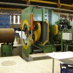
HYDROSTATIC PIPE TESTING MACHINE (HPTM)
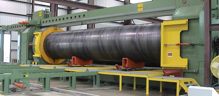
Having fully computerized controls, PRD Hydrostatic Pipe Testing Machines are suitable for pipe applications to meet any internationally known standards, including those of API and AWWA. Hydrostatic Pipe Testing Machines can be used with pipes produced by the electric resistance welding (ERW) process as well as pipes produced by the submerged arc welding (SAW) process.
The range covered with PRD HPTM s are:
Pipe Diameter to be Tested ½” (12.5 mm) to 120″ (3048 mm)
Pipe Length 4 meter to 20 meter
Max. Applicable Test Pressure 210 Bar
Max. End Load 3 000 Ton
Main HPTM components are:
“Tension Beams
“Head Stock
“Tail Stock
“Water Fill, Pressure and Vent System
“Pipe Lifting and Positioning System
“Control Station
TENSION BEAMS
Tension beams are made of one-piece rectangular steel plates and designed in such a way that the elastic limits of the material itself shall not be exceeded. Holes are provided at 250 mm increments in the beam for locking the tail stock at any required length of the pipe within the above specified range. Up to 4 tension beams are provided as per the required end load, 2 at the top and 2 at the bottom.
HEAD STOCK
The head stock is the stationary head of the HPTM and holds the seal plate. Tension beams are fixed to the head stock from the top. Water filling, pressurizing and venting occurs through the nozzles provided on the head stock.
TAIL STOCK
The tail stock is the moving head of the HPTM, driven by 4 hydraulic cylinders. The tail stock includes the counter seal holder and moves on the lower tension beams by means of hardened rollers. The fixing of the tail stock is provided by means of 8 hydraulically actuated load pins.
WATER FILL, PRESSURE and VENT SYSTEM
The pipe is filled by means of high-volume, low-pressure centrifugal pump(s). This initial filling is carried on up to the required volume of the water pumped. Then the high-pressure water pumps start – one pumps up to 80 bar, the second continues pumping until the test pressure is reached. Computerized controls allow the operator to extend the test period as long as necessary.
There are four valves in the system, namely
“Filling Valve, 4”
“Medium Pressure Valve 1” Stainless Steel
“High Pressure Valve 1”, Stainless Steel
“Air Relief Valve 1”, Stainless Steel
Within the foundation of the HPTM water are located reservoirs (with sedimentation chambers) and a centrifugal pump. This design allows for maximum cycling of the test water. There is no necessity for chemical additives in the reserved water. It is advisable to provide a separate pressurizing water tank with filtering system for longer life of the high-pressure pumps.
PIPE LIFTING and POSITIONING SYSTEM
Pipe positioning within the machine is provided by means of 2 lifting arms positioned on hydraulically driven cylinders. Cylinders can be controlled independently from each other to provide complete drainage and moved laterally to handle different length of pipes. The lifting arms are used to receive into the HPTM and to discharge the pipes to adjacent transferring units.
CONTROL STATION
All HPTM controls are computerized to allow a wide range of control options to the operator. All pipe positioning, tail stock movements, pipe filling and pressurizing sequence functions are controlled and enabled by means of computer. The operator may extend the pressurized test period as long as needed.
Use of the “learn mode” permits repeated testing of the pipes with the same characteristics without the intervention of the operator.
All test graphics can be observed on the monitor provided, printed and stored together with the test results in the required media (hard disk, floppy disk or CD).
SEAL TOOLING
The seal plate can be equipped for inside sealing, outside sealing and flanged sealing. The customer should specify desired sealing alternatives with order.
| Company / Location | Hydrotester Capacity | Year |
|---|---|---|
| Tumex Pachuca, Mexico | A.P.I., 14″ to 36″ Diameters AWWA, to 60″ 600 Tons End Load 6M to 12M Lengths | 1978 |
| S.I.M.E.T Bizerte, Tunisia | A.P.I., 6 5/8″ to 36″ Diameters AWWA, to 48″ 1000 Tons End Load 6M to 12M Lengths | 1981 |
| Shanghai Pacific Pipe Company Pudong, China | A.P.I., 8 5/8″ to 63″ Diameters AWWA, to 144″ 2200 Tons End Load 6M to 12M Lengths | 1988 |
| Shanghai Pacific Pipe Company Pudong, China | A.P.I., 8 5/8″ to 48″ Diameters AWWA, to 72″ 1200 Tons End Load 6M to 12M Lengths | 1993 |
| Kalup Corporation Tehran, Iran | 8″ to 80″ Diameters 2750 Tons End Load 6M to 12M Lengths | 1993 |
| Data Steel Pipe Industries (Pvt) Ltd. Rahim Yar Khan, Pakistan | A.P.I., 8 5/8″ to 60″ Diameters AWWA, to 72″ 1200 Tons End Load 6M to 12M Lengths | 1995 |
| Man Industries (India) Ltd. Indore, India | 18″ to 63″ Diameters 2200 Tons End Load 6M to 12M Lengths | 1995 |
| Ina Bromco Cia. Ltda. Quito, Ecuador | 16″ to 72″ Diameters 1000 Tons End Load | 1997 |
| Mannesman / Borusan, Turkey | 64″ Dia. 2000 Tons End Load 6M to 12M Lengths | 1999 |
| Sidergica de Tubo Saldado, SA / Spain | 100″ Diameter 7M to 16M Lengths | 2005 |
| Middle East Tube Company | 100″ Dia. 2200 Tons End Load 6M to 14M Lengths | 2006 |
| Gregorian International, Venezuela | 16″ to 60″ Diameters 6mm to to 25mm Material Thickness 6M to 12M Pipe Lengths | 2007 |
